Follow fuel, energy and the command separately
Trace three paths through an injection system. Fuel travels from the supply side to the injection equipment and, where designed, through return circuits. The energy path supplies the work needed to raise pressure. The command path determines when and how the equipment operates. These paths interact, but an electrical signal is not the source of all the hydraulic energy in a diesel injection event.
The injector must deliver an appropriate quantity with suitable timing and spray formation for the engine's operating condition. Injection pressure, duration and delivered quantity are related, but they are different quantities. The same command duration does not guarantee the same fuel delivery when pressure or component behaviour changes. Air supply, compression and combustion conditions also matter, so an engine symptom cannot be assigned to an injector from its name or appearance alone.
Common Rail separates pressure generation from the injection event
In a Common Rail system, a high-pressure pump supplies a shared accumulator called the rail. The rail distributes pressurised fuel to the injectors. The engine controller uses information about operating conditions to command injection, while pressure-control functions manage the fuel supply and rail pressure. The rail also provides hydraulic storage; it is not simply an electrical distribution component.
This arrangement separates the task of producing pressure from the timing of each individual injection. It does not mean pump speed, available delivery or hydraulic disturbances become irrelevant. The controller can only request operation within the system's actual capabilities, and rail pressure can change as pump delivery, injection demand and return flows change. A low rail-pressure reading therefore describes a system condition, not automatically a failed pump. Supply restrictions, control behaviour, leakage and measurement information have to be considered in the appropriate diagnostic procedure.
An injector bench reproduces selected hydraulic and electrical conditions. It does not reproduce every engine influence, such as cylinder compression or the complete vehicle wiring installation.
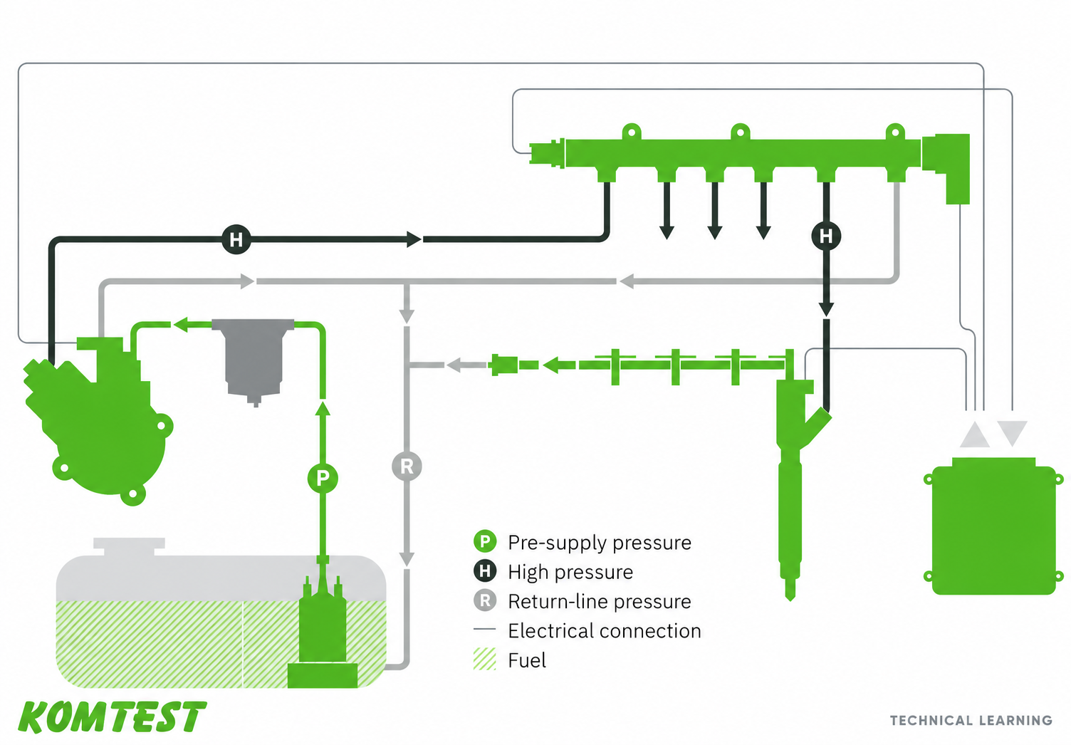
P identifies pre-supply pressure in green, H high pressure in charcoal, and R return-line pressure in gray. Thin lines show electrical connections. This educational reference shows one system arrangement; component layout and control functions vary by application.
Open the full-size image (new tab)EUI and EUP generate pressure locally
An electronic unit injector, or EUI, combines a pumping element and injection nozzle in one assembly. In the cam-driven arrangement, a cam and its mechanical transmission move the pumping element. Electronic control determines the effective injection event through the injector's control mechanism. The injector therefore receives both mechanical energy and an electrical command; calling it electronic does not mean it lacks a mechanically driven pumping action.
An electronic unit pump, or EUP, places the individual pumping unit separately from the nozzle holder. A matched high-pressure pipe connects them. There is typically one pumping unit for each cylinder rather than a shared Common Rail accumulator supplying every injector. Pipe and nozzle characteristics belong to the system's hydraulic behaviour, so a pump cannot be evaluated meaningfully with an arbitrary replacement connection and an unrelated test plan.
Both arrangements require the relevant drive and control conditions during testing. A suitable fixture must do more than hold the component: it must establish the intended mechanical relationship and hydraulic connections for the particular application.
| Arrangement | Where pressure is generated | Useful distinction |
|---|---|---|
| Common Rail | Separate high-pressure pump supplying a shared rail | Injection is commanded from an available pressurised fuel supply. |
| Cam-driven EUI | Pumping element integrated with the nozzle | Mechanical drive and electronic control act on one injector assembly. |
| EUP | Individual pumping unit connected to a separate nozzle holder | The matched high-pressure connection is part of the arrangement. |
| HEUI | Injector intensifier driven by pressurised oil | Actuation oil and injected fuel have different functions. |
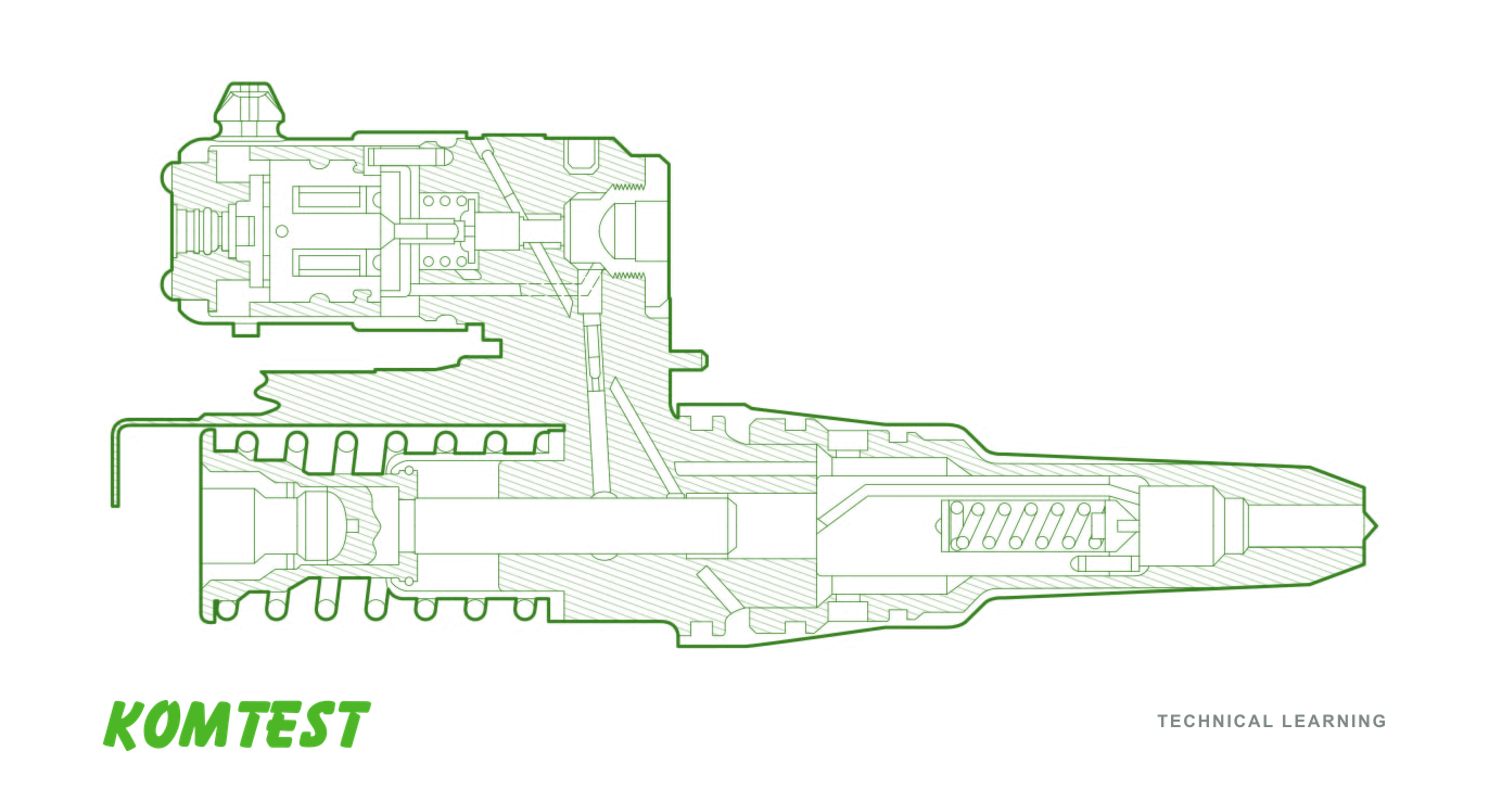
An educational sectional reference of a unit injector, with the pumping element and nozzle in one assembly. This is a particular component design, rather than a universal internal layout for every EUI.
Open the full-size image (new tab)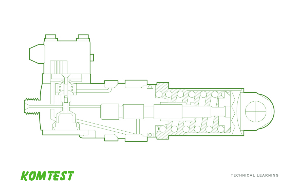
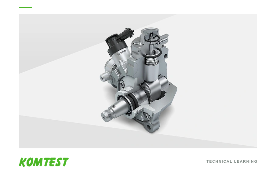
An educational reference showing a separate unit-pump assembly in section. The nozzle holder and matched high-pressure connection discussed in the text are outside this component view.
Open the full-size image (new tab)HEUI uses hydraulic actuation and electronic control
HEUI means hydraulically actuated, electronically controlled unit injection. In this arrangement, pressurised engine oil supplies actuation energy to an intensifier mechanism in the injector. That mechanism raises the pressure of the fuel for injection. The engine controller operates the injector's control valve, and the oil-actuation system helps determine the conditions under which the fuel is injected.
Actuation oil and fuel must be understood as separate functional circuits. Oil is not the fuel being sprayed into the combustion chamber, and the oil pressure must not be described as though it were automatically equal to injection-fuel pressure. The intensifier and the particular injector design govern their relationship. Likewise, an oil-side operating problem and a fuel-side supply problem are different diagnostic possibilities even when both affect injection.
Testing a HEUI injector requires suitable oil-side and fuel-side conditions as well as the correct control strategy. A Common Rail pressure connection alone does not reproduce its operating principle. The exact fluid requirements, temperature conditions, fixtures and test points must come from the applicable equipment and component procedure.
Solenoid and piezo identify the actuator
A solenoid uses an electromagnetic field to move an armature or operate a control mechanism. A piezo actuator uses the change in dimensions of a piezoelectric stack when an electrical drive is applied. The movement is used within the injector's mechanical and hydraulic design to control injection. Depending on the injector, the actuator may operate a hydraulic control valve rather than directly lifting the nozzle needle.
These terms answer a different question from Common Rail, EUI or HEUI. Common Rail describes the pressure-supply architecture; solenoid and piezo describe how an actuator works. Common Rail injectors can use either technology. The presence of an electrical connector does not identify the complete architecture, the required driver, or the injector's coding method.
An actuator label is also insufficient to select electrical tests. The correct driver strategy and permitted checks depend on the component design. A resistance value or drive signal suitable for one family must not be assumed appropriate for another. Identify the exact reference and procedure before deciding how a component should be evaluated.
Use the architecture to ask better testing questions
Before interpreting a result, establish the component's exact identity, pressure-generation arrangement and intended control method. Then ask what the test actually reproduces and measures. A result may concern delivered fuel, return flow, response or another specified characteristic. Each result belongs to defined operating conditions and acceptance criteria; a component passing one point has not automatically been assessed over every possible condition.
Vehicle diagnosis and component testing supply different evidence. Vehicle work can examine the interaction between sensors, electrical circuits, air handling, compression and the complete fuel system. A bench can isolate selected component behaviour with controlled inputs. Their findings should be connected through the diagnostic question, rather than using either one as a substitute for the other.
For a useful workshop enquiry, record the engine application, the complete component reference, the reported concern and any existing diagnostic or bench results. Those details help determine the relevant test method. A visible match between connectors, a similar system name or a general claim about a brand is not enough to establish interchangeability or test coverage.
KOMTEST Technical Learning
Key takeaways
- Locate pressure generation before choosing the test method.
- Keep electrical control distinct from the source of pumping energy.
- Interpret a component result within its test plan and the wider vehicle diagnosis.
Questions & answers
A closer look.
Is every electronic diesel injector a Common Rail injector?
No. Electronic control also appears in unit-injector and hydraulically actuated systems. The location and method of pressure generation identify the architecture more reliably than the presence of a connector.
Is HEUI oil pressure the same as injection pressure?
No. Oil supplies actuation energy to an intensifier that pressurises the fuel. The relationship depends on the injector design and operating conditions; the two pressures describe different circuits.
Can one successful injector test rule out all causes of poor engine running?
No. It supports a conclusion about the characteristics assessed under the stated test conditions. Engine, installation, electrical and other fuel-system influences still require their own evidence.
Technical glossary
- Rail
- A shared high-pressure fuel accumulator and distributor in a Common Rail system.
- Actuator
- A device that converts a control input into movement within a mechanism.
- Intensifier
- A hydraulic mechanism that transfers force between piston areas to raise pressure in another circuit.
- Test plan
- A defined set of operating conditions, measurements and evaluation criteria for a particular component or application.